
The Gen2 camera ITS-in-a-box consists of an aluminium box that's laser cut from computer-aided design (CAD) drawings, a printed test chart, and a device under test (DUT). The Gen2 camera ITS-in-a-box has the same capabilities as the regular camera ITS-in-a-box but includes a three-stage lighting system with high-quality LED modules, an improved motor that's robust and provides feedback, and full metal construction to improve structural rigidity and reduce light leakage.
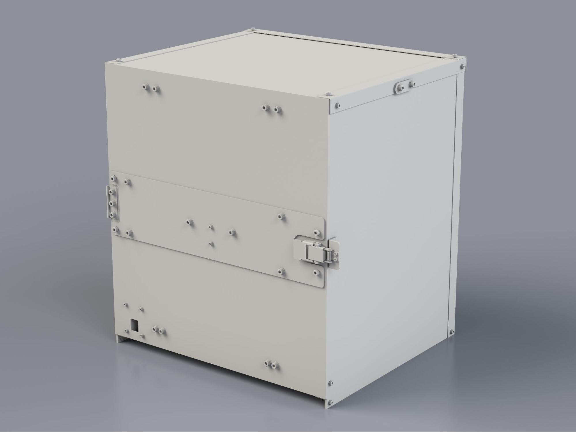
Figure 1. Gen2 camera ITS-in-a-box.
How to use the Gen2 camera ITS-in-a-box
To use the Gen2 camera ITS box, follow these steps:
- Purchase the Gen2 ITS box.
- Set up the controller and mount the DUT.
- Run the camera ITS tests.
- Retrieve the results from the DUT.
Purchase a Gen2 camera ITS-in-a-box
We recommend purchasing the Gen2 camera ITS-in-a-box from one of the following qualified vendors.
Wuxi BioHermes Bio&Medical Technology Co., Ltd.
China: 88 West Meiliang Road. Mashan. Wuxi, Jiangsu 214092
http://www.biohermes.com
luweijie@biohermes.com.cn
China: +86-510-85385897 ext 2121Byte Bridge Inc.
USA: 1502 Crocker Ave, Hayward, CA 94544-7037
China: 22F #06-08, Hongwell International Plaza Tower A, 1600 West Zhongshan Road, Xuhui, Shanghai, 200235
https://www.bytebt.com
androidpartner@bytebt.com
USA: +1-510-373-8899
China: +86-400-8866-490
Set up the chart for testing
Before testing, check the Gen2 rig chart as fingerprints and scratches on the chart can negatively affect test analysis. If the chart is damaged or doesn't include all of the features in the following image, install a new chart.

Figure 2. Gen2 chart.
The Gen2 chart is revised in Android 17 to support sensor fusion tests. You can order a Gen2-26Q2-0.0 rig with the revised chart from a qualified vendor or install the revised chart on an existing Gen2 rig.
To install the revised chart on an existing rig:
- Contact your Gen2 rig vendor for the revised chart.
- Cover the edges of the back side of the chart with double-sided tape. Tape that is around 1.25 mm thick is ideal.
- Align the chart to the back of the Gen2 rig, keeping it centered. Attach the chart on one side and press firmly from one corner to the other corner. Do the same for adjacent sides until all four sides are attached to the rig. You can tape over screws, as long as the center of the chart is flat.
Video tutorial
This is a video tutorial of how to set up the Gen2 camera ITS-in-a-box:
Set up the controller for testing
Follow these steps to set up the Gen2 camera ITS-in-a-box controller for testing.
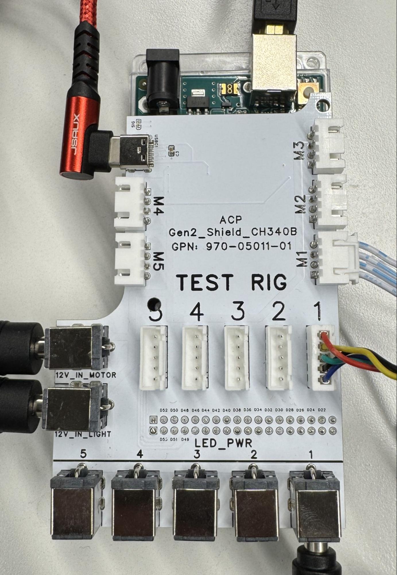
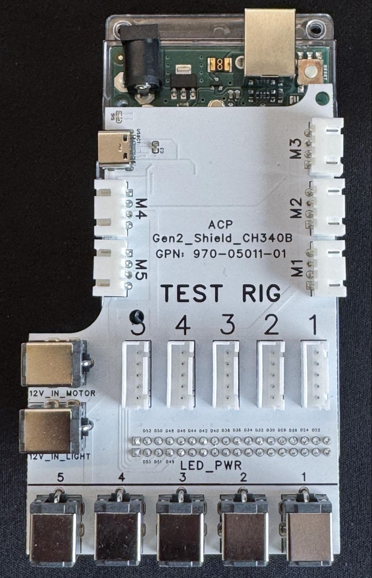
Figure 3. Gen2 controller with (left) and without connections (right).
- Place the Gen2 rig at your selected location.
Connect the cables to the appropriate ports as follows:
- 4-pin cable to the M1 port.
- 5-pin cable to the TEST RIG - 1 port.
- Barrel plug to the LED_PWR - 1 port.
- Barrel plugs of the two power supplies to the 12V_IN_MOTOR and 12V_IN_LIGHT ports.
- USB-A to USB-C cable to the M4 USB-C port.
- USB-A to USB-B cable to the M3 USB-B port.
- Power cords from the power supplies to a power outlet.
- USB-A end of the USB-A/C and USB-A/B cables from the controller to your host.
The controller firmware is available at gen2_production_v2.ino.
Configure host permissions
To allow the host computer to communicate with the Gen2 controller and motor
through USB serial ports (such as /dev/ttyACM* or /dev/ttyUSB*), ensure your
user account has the required permissions:
Add the user account running the tests to the
dialoutgroup:sudo usermod -aG dialout $USERLog out and log back in (or reboot the host machine) for the group change to take effect.
Verify that your user is part of the
dialoutgroup:groups | grep dialout
sudo systemctl stop ModemManager
sudo systemctl disable ModemManager
Servo and controller reliability testing
This section outlines the method of performing reliability testing for Gen2 camera ITS-in-a-box rigs. The purpose of running the reliability test script is to qualify critical parts of the rig and eliminate infant mortality risk for the rigs by cycling all the moving parts within the rig and reporting on potential issues with the quality of parts or assembly. Reliability testing as outlined takes less than five minutes of execution time and is highly recommended as soon as the rig is delivered and set up.
Hardware description
To execute the reliability test script, the manufacturing rig must meet the following specifications:
- Controller: The custom controller PCB (USB-to-serial adapter using the CH340 chipset)
- Servo: Lynxmotion Smart Servo (LSS) HT1 connected to the controller board
- Baud Rate: 115200
- Power: External power supply capable of sustaining peak current for the specific LSS model used - 12V - 10A
Automated test sequence
The reliability stress test script (Gen2_ITS_Motor_Cycling.py) automates the
following two-phase stress test. Each phase performs 50 full cycles (100
movements per phase).
| Phase | Motion range | Speed or interval | Purpose |
|---|---|---|---|
| Initialization | Move to 0° | 2 second delay | Establishment of a neutral baseline. |
| Phase 1: Macro move | -90° ↔ +90° | 2 second interval | Gear train travel and potentiometer consistency and PCB stress test. |
| Phase 2: Micro move | -15° ↔ +15° | 0.25 second interval | High-speed direction reversals and motor thermal load and PCB stress reliability. |
Execution instructions for operators
- Ensure that the Python environment has pyserial (
pip install pyserial) and thelsslibrary (included with the zip file) installed. - Connect the PCB controller to the PC and the LSS servo to the controller and power as per nominal configuration.
- Download and extract
ServoReliability_Gen2ITS.zip. Navigate to the extracted
ServoReliability_Gen2ITSfolder in a terminal window and run:python Gen2_ITS_Motor_Cycling.pyMonitor the script, which outputs Current Position in real time. Verify that the physical movement roughly matches the degrees printed in the terminal.
The script generates a unique validation code (for example, 4R24EM). You can record this code against the assembled rig for future use.
Automated reporting
The script automatically generates a time-stamped log file in the ./Reports/
directory.
- Filename format:
TestReport_[Timestamp].txt - Log data: Includes port detection, connection status, per-cycle position telemetry, and the final validation hash.
Pass or fail criteria
While the script checks for software connectivity, you must fail the unit if any of the following occur during the 100 cycles:
- The Bus closed message doesn't appear or the script hangs, retrying the connection indefinitely.
The Current Position reported by the servo deviates more than 45 degrees from the commanded target, which indicates a slipping gear or internal encoder error.
Controller Not Connected error messages appear in the terminal.
Troubleshooting: Connectivity and drivers
If the script returns the message Controller Not Connected, follow these steps to resolve the hardware interface:
- USB connections: Ensure that the USB-C cable used to connect the computer to the PCB controller is seated properly on both ends and is working correctly.
- Driver requirement: The rig must have the WCH CH341/CH340 serial driver installed. This is usually installed by default for Windows, Mac, or Linux systems.
On Linux or Ubuntu, ensure that the user has permissions to the
dialoutgroup:sudo usermod -a -G dialout $USER
Common script errors
This section lists some common script errors.
Found CH340 at: None
- Likely cause: Hardware not recognized.
- Solution: Check the USB cable and ensure the Vendor ID (0x1A86) matches the hardware.
Error connecting: [Errno 13] The port is busy.
- Likely cause: Another program is using the COM port.
- Solution: Close any other serial monitors or IDEs using the COM port.
Bus closed (immediately)
- Likely cause: LSS library failure.
- Solution: Ensure that
lss.pyandlss_const.pyare in the same directory as the test script.
Operational safety notes
Keep the following points in mind while running the reliability test script to ensure the safety of the person involved as well as the integrity of the equipment:
- Cable strain: Because Phase 2 executes 50 cycles at a 0.25 second interval, ensure the servo wiring has enough slack to prevent tension during rapid oscillations.
- Emergency stop: To terminate the test manually, press Ctrl+C while in
the terminal window. The
finallyblock in the script attempts to close the LSS bus safely before exiting. - Log preservation: Don't rename the
./Reports/folder, as the script relies on this relative path to save the validation data.
Frequently asked questions (FAQs)
The following are frequently asked questions about the Gen2 camera ITS-in-a-box.
Chart
Q: My chart is damaged, how can I get a new chart?
A: To get a new chart, reach out to one of our qualified vendors, Biohermes or Byte Bridge Inc.
Q: Do I have the correct chart?
A: There are two versions of the chart. Figure 4 shows the chart designed
for scene_ip testing (left) and the chart designed for
scene_ip, sensor_fusion, and scene_flash testing (right).
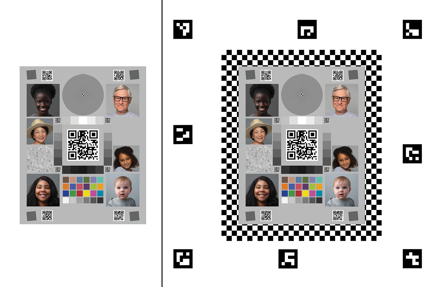
Figure 4. Chart versions.
Motor
Q: My rig connects, but the motor doesn't maintain its position. Is this normal?
A: Yes, this is normal in the initial test cycle. After the initial test cycle is complete, the motor maintains its position.
Q: How is the LSS-HT1 motor in the Gen2 rig different from the HS-755MG motor in the sensor fusion rig?
A: The LSS-HT1 motor in the Gen2 rig improves the accuracy, precision, build quality, and feedback of the rig. The motor also provides extensive parameter controls.
Q: My motor flashes and doesn't move. What should I do?
A: This indicates that an obstruction is blocking the motor. Inspect the DUT
and rotating plate for obstructions or tangled cables. After resolving the
issue, send the command #0RESET<cr> to reset the motor and continue
testing.
Q: Where can I find a datasheet for the motor (LSS-HT1)?
A: You can find documentation on the LSS-HT1 motor at the Lynxmotion website.
LED
Q: How do I determine if my LED bars install correctly?
A: Refer to Figure 5 for an example LED bar installation. Ensure that the white line on the LED board aligns with the 3D-printed holder, and the LEDs are connected and seated correctly.
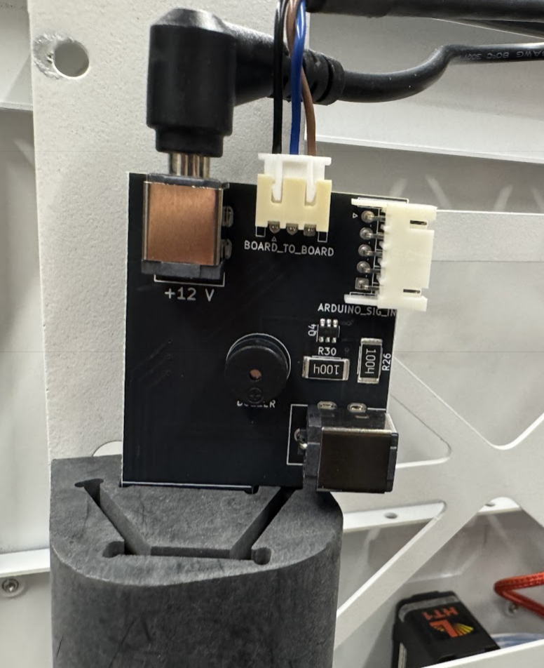
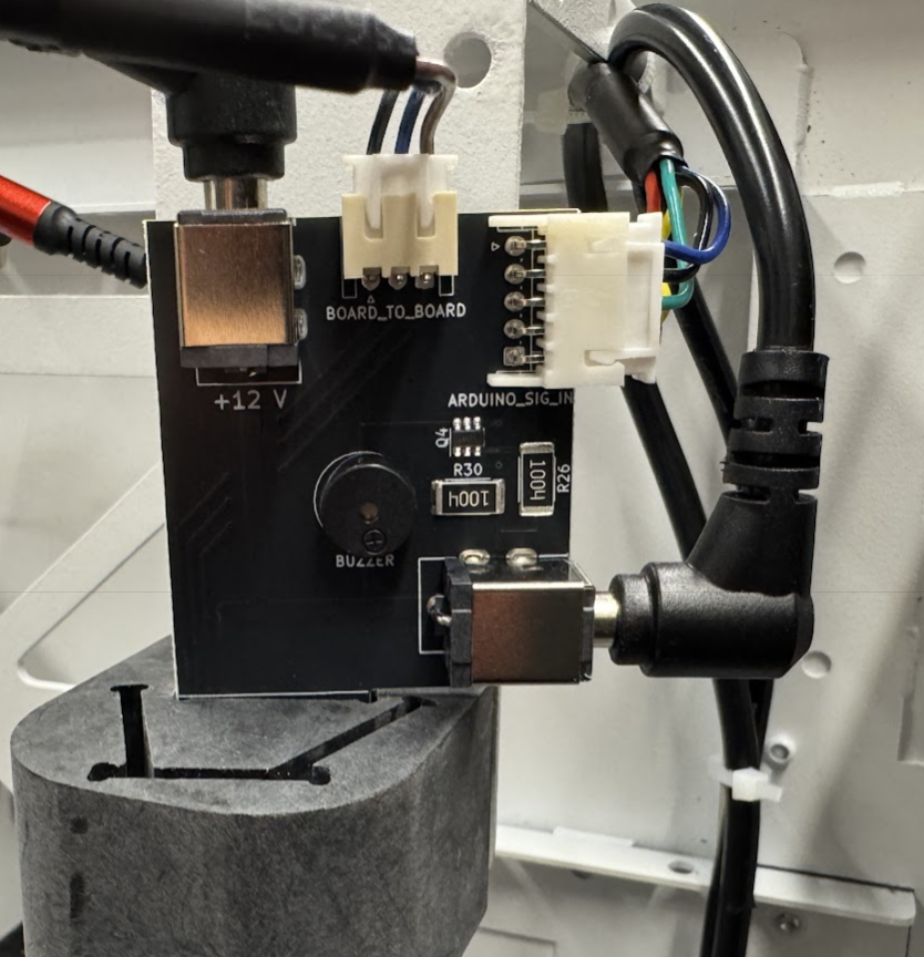
Figure 5. LED bar installation with (left) and without connections (right).
Controller
Q: What are the designated channels for the motor and LEDs?
A: Channel 0 for the motor. Channel 1 for the LEDs.
Q: How do I test the hardware?
A: Send the command f11 to the controller (Arduino Mega) to initiate a
test sequence for the lighting. The sequence cycles through three distinct
lighting stages and briefly activates the buzzer multiple times. To test the
motor, use the Lynxmotion LSS configuration software available from
Lynxmotion.
Q: When running tests, I get a Permission denied or could not open port
serial error. What should I do?
A: Ensure that your user account has been added to the dialout group as
described in Configure host permissions. Also verify that background
services such as ModemManager are disabled and not locking the USB serial
port.